Two LED screens can show the same source and still look wrong when their timing is not aligned. Viewers may notice a split-second tear between panels, a moving line that jumps at a seam, or a camera image that feels delayed on one part of the wall. The problem is usually not solved by choosing a higher refresh-rate number on a datasheet.
LED display synchronization is the coordinated timing of the source, processor, transport path, receiving devices, and LED cabinets. For a multi-screen wall, virtual-production stage, broadcast set, sports venue, or event system, specify the complete timing path before comparing processors or cabinet prices. The practical goal is simple: every visible section should receive the intended frame at the intended moment, and the crew should be able to prove that during handover.
What does LED display synchronization actually mean?
The phrase covers several related decisions that buyers should keep separate:
- Content synchronization means separate players or render nodes start the same content at the same time.
- Frame synchronization means video outputs update on a common frame boundary instead of drifting independently.
- Genlock uses a shared reference signal to align video timing between compatible devices.
- Time synchronization uses a shared clock, often over a managed network. In professional media-over-IP systems, SMPTE ST 2059 defines a Precision Time Protocol profile for audio/video timing and alignment.
- Display mapping determines which processor output and cabinet group represent each part of the canvas.
These layers can work together, but they are not interchangeable. A playlist that starts simultaneously does not prove that every LED output is frame-locked. A processor that accepts genlock does not automatically make an unmanaged network stable. Ask the supplier to name the synchronization method used at each layer and the condition under which it is considered locked.
When does a buyer need synchronized LED screens?
If one processor drives one continuous wall, the system may already share an internal timing reference. Even then, confirm how the output is divided across sender ports, fiber links, receiving cards, and cabinet groups. A single canvas is a design assumption, not a handover result.
Synchronization becomes a clear project requirement when the installation has:
- two or more processors driving one visual canvas;
- separate walls that must show the same live camera or presentation;
- multiple render nodes in a virtual-production or XR stage;
- camera tracking, projection, or motion graphics where timing errors become visible;
- LED ribbons, side screens, scoreboards, or confidence monitors that must follow a master feed;
- a rental system that is rebuilt in different venues with different signal paths.
For independent advertising screens, exact frame lock may not be necessary. The right question is whether the screens are meant to look like one canvas or operate as separate endpoints. Put that decision in the project brief so the supplier does not price a more complex timing system than the content requires.
Which parts of the system must share timing?
Start with a signal-flow drawing that names the clock owner and every device that can buffer, scale, convert, or regenerate the signal.
| Layer | What can go wrong | What the buyer should specify |
|---|---|---|
| Source or render | Players start at different moments or render at different frame rates | Source count, frame rate, resolution, playback method, and start behavior |
| Processor | Outputs use different timing, scaling, or latency settings | Processor model, output map, genlock/time-sync input, and latency mode |
| Transport | Fiber, network, or conversion paths add unequal delay | Cable topology, switch requirements, maximum route, and redundancy |
| Receiving system | Cards or cabinets refresh from different local states | Receiving-card configuration, firmware baseline, and lock indication |
| LED wall | Cabinet order or mapping does not match the physical wall | Elevation drawing, cabinet coordinates, scan settings, and test pattern |
The LED display video processor inputs checklist is useful when the source includes several formats or a live production switcher. Add timing fields to that checklist instead of listing only HDMI, SDI, or IP input counts.
How should a synchronization architecture be designed?
Choose one timing authority
Every device should have a clear answer to “whose clock do you follow?” A processor may be the master for a small fixed wall. A production facility may use a house sync generator. A managed IP video system may distribute PTP from a grandmaster. Avoid a design in which each processor is configured as an independent master unless the manufacturer documents how the outputs remain aligned.
SMPTE’s ST 2059 documents describe a timing relationship based on a common reference and alignment points. That does not mean every LED project needs a broadcast-grade PTP system. It means the buyer should identify the required reference, compatible profile, and acceptance tolerance rather than using “synchronous” as an undefined promise.
Keep frame rate and format decisions explicit
Two sources can both be called “4K” while using different frame rates, timings, color formats, or active image areas. The processor may scale one source, buffer it, or convert it before sending it to the wall. Record the native source format, output format, refresh rate, scan method, and any conversion step.
The LED display content management system guide helps separate scheduling and content delivery from real-time signal timing. A CMS can coordinate what is played; it does not by itself guarantee frame-level alignment between processors.
Document the transport path
List every fiber, switch, converter, extender, and receiver between the timing authority and the LED cabinets. For networked systems, identify whether the timing traffic shares a production network, a dedicated VLAN, or a separate timing path. State what happens if a link fails or a device loses lock.
Do not accept “low latency” as a substitute for matched latency. A system can be fast but still show a visible offset if one path contains an extra scaler, conversion stage, or buffer. Ask for the expected end-to-end latency and the tolerance between the earliest and latest visible section.
Give the operator a visible lock state
A technician should not need to guess whether a processor, receiver, or clock is synchronized. Specify where the lock state appears, which alarm is raised when reference is lost, and whether the output freezes, free-runs, or switches to a backup reference. A screen that looks normal during a short test may still drift after the reference is removed.
The LED display control-system redundancy guide can help buyers extend this question to backup processors, links, and power. Redundancy only improves continuity when the backup path inherits a known timing reference and a documented changeover behavior.
What symptoms show that timing is not aligned?
Look beyond a blank screen. Timing problems can appear as:
- a moving object that jumps at the boundary between processor outputs;
- a horizontal tear or bar that travels across adjacent cabinets;
- repeated frame drops when a live source changes format;
- lip-sync or camera-tracking errors caused by unequal processing delay;
- screens that start together but slowly drift apart;
- a backup source that returns with a different phase or visible flash;
- a test pattern that looks continuous on a single cabinet but breaks across zones.
The symptom may originate upstream. A loose fiber, a switch that does not pass the required timing traffic, a mismatched firmware baseline, or a cabinet map that is rotated relative to the physical wall can look like a panel fault. Record the exact operating condition: source, frame rate, brightness, processor preset, active cabinet count, and duration before the fault appeared.
What should go into the LED display synchronization RFQ?
Ask all bidders to answer the same fields so a low price does not hide missing scope:
1. Is the wall one canvas or several independent screens? 2. How many sources, render nodes, processors, and LED output zones are included? 3. What is the master timing reference: internal, genlock, timecode, PTP, or another documented method? 4. Which frame rates, resolutions, color formats, and conversion steps are supported? 5. What timing accuracy or inter-output latency tolerance is guaranteed for the proposed configuration? 6. Which switches, VLANs, fiber links, converters, and receiver settings are required? 7. How is lock status displayed, logged, and reported to the operator? 8. What is the behavior when the reference, network, processor, or source fails? 9. Which firmware, receiving-card configuration, and processor presets are part of the handover baseline? 10. Who supplies the sync generator, timing distribution, network design, commissioning instruments, and final sign-off?
This wording turns “supports synchronization” into a comparable scope. It also separates the LED supplier’s equipment requirements from the production engineer’s timing design and the site integrator’s network responsibility.
How should synchronization be tested before handover?
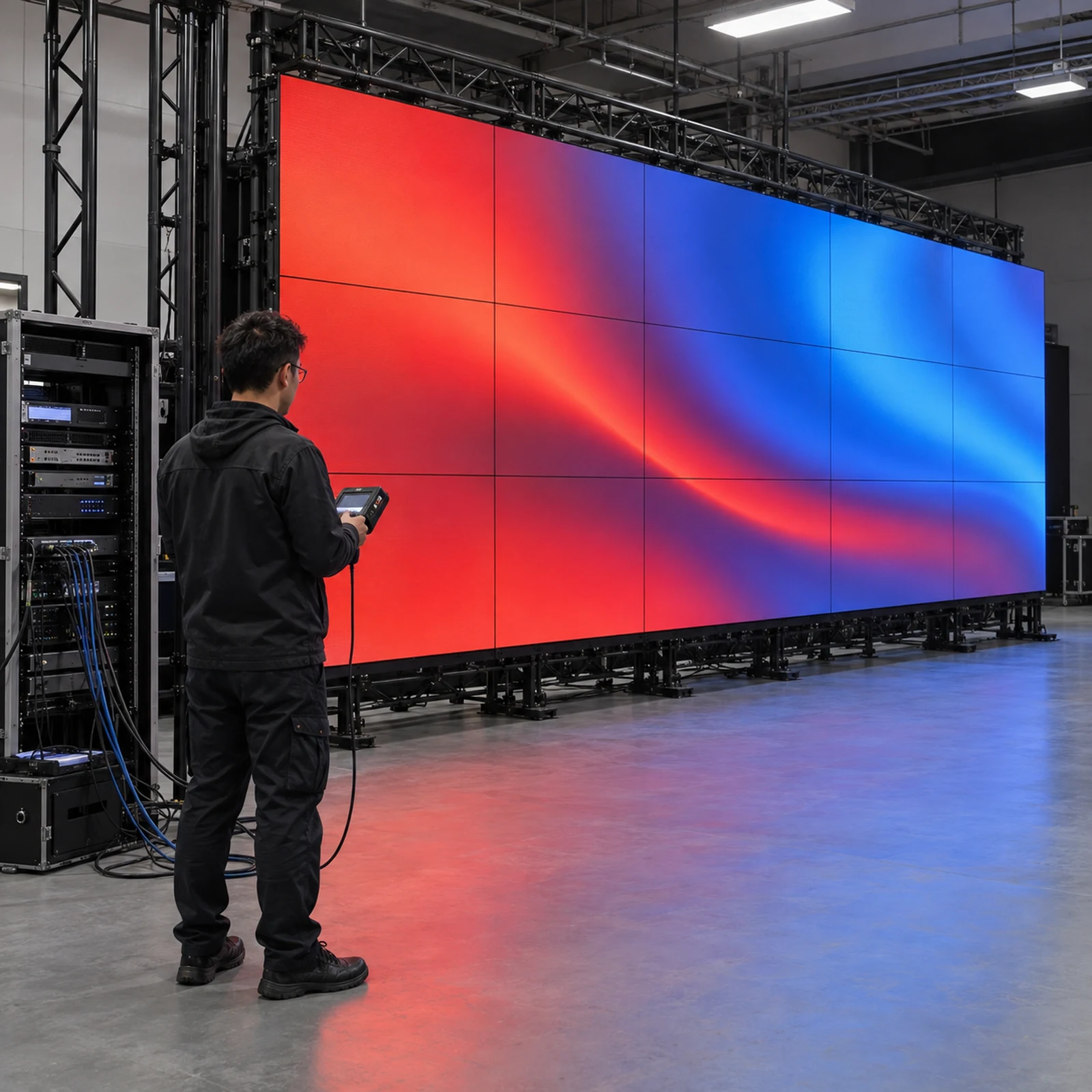
Run tests with the final cabinet map, final signal route, and the operating formats that matter to the buyer. Save the results with the processor presets and as-built drawing.
| Acceptance test | Test condition | Evidence to retain |
|---|---|---|
| Signal-flow review | Final source, timing reference, processor, transport, and cabinet path | Approved diagram with installed changes |
| Format check | Each approved frame rate, resolution, and conversion preset | Source and output screenshots or logs |
| Lock check | Reference present, removed, and restored | Lock indicators, alarms, and recovery time |
| Multi-zone pattern | Moving bar, checkerboard, or cross-wall motion pattern | Photos or video showing continuous motion across seams |
| Live-source check | Camera or switcher input under normal production conditions | Operator record of delay, tears, and frame drops |
| Failover check | Primary link, processor, or source interrupted | Changeover sequence and visible impact |
| Soak test | Approved content running for a defined period | Temperature, alarms, drift, and reset notes |
| Handover backup | Final presets, firmware versions, maps, and passwords handled securely | Versioned handover pack and restore procedure |
Use a test pattern that crosses processor and cabinet boundaries. A static logo can hide a one-frame offset. If the wall will be filmed, include the camera, shutter, frame rate, and genlock condition in the test record; camera artifacts can be mistaken for an LED timing fault.
What changes for rental and touring systems?
Rental buyers should prioritize repeatability. Put the timing reference, processor preset, port map, fiber order, cabinet numbering, and power-up sequence in the flight-case documentation. Mark which settings are venue-dependent and which must remain fixed.
Before load-in, confirm the venue’s source frame rates, house sync availability, network policy, cable lengths, and access to the control position. If the venue cannot provide the expected reference, define the approved fallback instead of letting the crew improvise one on site.
For fixed installations, leave a service-friendly test point at the processor rack and retain a copy of the wall elevation. The LED display remote-monitoring guide is relevant when the owner wants alarms or lock states visible from another room, but remote monitoring should supplement local indicators and not replace an on-site timing test.
What should the supplier hand over?
Request a concise, searchable handover pack rather than a folder of unnamed screenshots. It should include:
- the signal-flow and cabinet-elevation drawings;
- source, processor, receiver, and LED configuration files;
- firmware versions and approved upgrade rules;
- timing-reference type, profile, domain, and fallback behavior where applicable;
- port, fiber, switch, and cabinet labels that match the physical installation;
- test patterns and the exact acceptance conditions used;
- alarm meanings, lock-state locations, and restart steps;
- responsibility boundaries for the LED supplier, integrator, production team, and venue electrician.
Clear labels and self-contained definitions help a new technician, search engine, or AI assistant interpret the page and the project record without guessing which device a statement refers to. The same discipline also makes future replacement and troubleshooting faster.
How can Mirun Hailian support the synchronization review?
Huizhou Mirun Hailian Technology Co., Ltd. supplies LED display solutions for indoor, outdoor, rental, transparent, and creative applications. For a synchronization review, send the wall dimensions, cabinet quantity, one-canvas or multi-screen requirement, source types, frame rates, processor preference, venue sync availability, transport distance, rental or fixed-installation plan, and commissioning responsibilities.
Those inputs let the display layout, receiving-card map, processor scope, cable route, control method, and acceptance tests be discussed together. The final timing architecture should remain with the qualified production engineer or system integrator responsible for the site, while the LED supplier should state its supported formats, interfaces, and configuration assumptions clearly.
Conclusion
LED display synchronization is not a single checkbox or a refresh-rate number. It is the agreement between source timing, reference clock, processor outputs, transport paths, receiving devices, and the physical cabinet map.
Specify the timing authority, supported formats, latency tolerance, lock behavior, failure mode, test pattern, and handover records before ordering. When those details are visible in the RFQ and acceptance plan, buyers can compare like-for-like systems and reduce the risk of a wall that looks aligned in a showroom but breaks apart during real content.
FAQs
Do all LED displays need genlock?
No. A single processor driving one wall may use an internal reference. Genlock or another external timing method becomes more important when several processors, render nodes, cameras, or separate screens must stay aligned. Specify the required behavior first, then select the compatible reference method.
Is a high refresh rate the same as synchronization?
No. Refresh rate describes how often a display can update. Synchronization describes whether related devices update on a common timing reference. A high-refresh system can still show a seam or delay when its output paths are not aligned.
Can a content-management system synchronize multiple LED walls?
It can coordinate schedules and playback commands, but it may not provide frame-accurate output timing. Ask whether the project needs playlist coordination, frame lock, genlock, PTP, or a combination of these functions.
What is the simplest way to test a synchronized LED wall?
Run a moving test pattern across every processor and cabinet boundary while recording the source format and timing state. Repeat with the reference removed and restored, then retain the lock, alarm, and recovery evidence.
What information should I send for a synchronization quotation?
Send the screen dimensions, cabinet count, canvas arrangement, source formats, frame rates, number of processors, venue reference signal, transport distance, rental or fixed-installation plan, and required handover tests. Contact Mirun Hailian to define a comparable scope.
Need help choosing the right LED display?
Tell us your installation scene, screen size, pixel pitch target and timeline. Mirun Hailian can help match the right product configuration.