Nobody wants to explain a black LED screen to a client, an audience, or a control-room operator. Yet plenty of B2B quotes still treat the control system as one processor, one signal route, and one power feed. It works perfectly until one small failure takes the whole display offline.
That is why LED display control system redundancy should be discussed before the purchase order, not after installation. A good plan does not simply add a second box to the rack. It identifies the failures that matter, decides what should switch automatically, and gives the acceptance team a practical way to prove that the backup path works.
Start with the business consequence, not the hardware
Redundancy is not an automatic yes-or-no requirement. A lobby screen that can be restarted after ten minutes has a different risk profile from a televised event, a command center, or a stadium scoreboard. Before asking suppliers for backup equipment, answer one plain question: what happens to the business if the screen goes dark?
- How long can the screen be unavailable before operations are affected?
- Is a manual switch acceptable, or must failover be automatic?
- Does the whole screen need protection, or only critical zones?
- Will trained staff be present when the display is running?
- Does the project need a temporary fallback image, a fully live backup, or both?
Put those answers in the LED display project brief. Otherwise, two suppliers may both quote “redundancy” while proposing completely different protection levels.
Map the entire signal chain
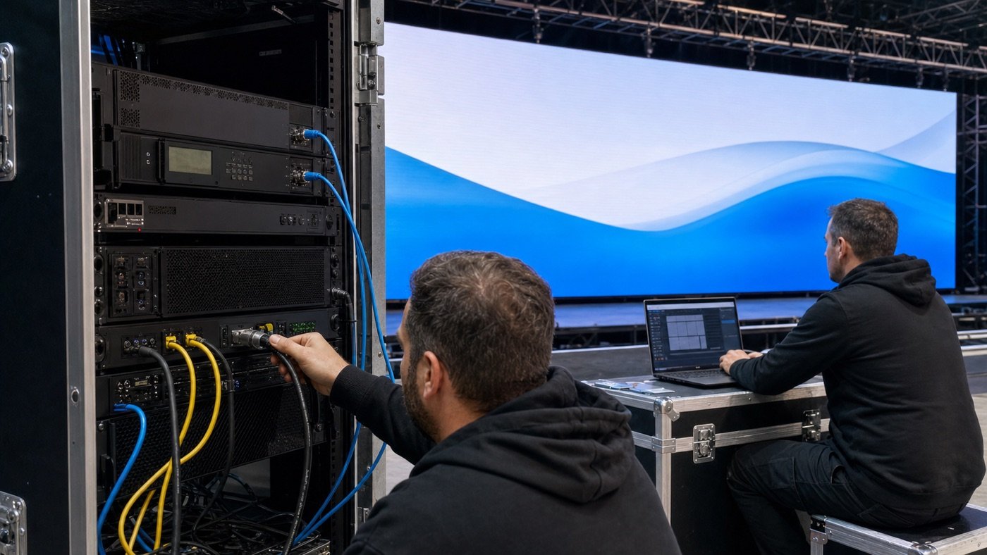
Most buyers focus on the main video processor because it is easy to see on a quotation. The real signal chain is longer: content source, switcher, processor, fiber converter, network cable, receiving card, module, power supply, and the software or operator controlling it all. Any single unprotected point can cancel the value of the backup processor.
Ask the supplier for a one-line signal diagram showing both the primary and backup paths. The drawing should identify ports, cable types, cabinet groups, equipment locations, power sources, and the expected switching method. If the backup line shares the same switch, cable route, outlet, or damaged rack, it may not be as independent as the quote suggests.
Five redundancy layers buyers should review
1. Content source and video input
A spare processor cannot help if the only playback computer freezes. For high-consequence projects, confirm whether there is a second playback source, a backup input, or a switcher that can move to a known-good signal. The backup content should use the correct resolution, frame rate, and color settings before the event starts.
2. Processor or controller
Processor redundancy usually means a primary unit and a compatible backup with synchronized configuration. But the details vary by product family. For example, NovaStar’s official COEX backup instructions describe protection across controllers, fiber links, Ethernet cables, and modular output cards. That is a product-specific design, so buyers should verify the exact model, firmware, license, and supported topology in their own quote.
3. Fiber and Ethernet transmission
A second controller feeding the same cable is not a complete backup. Ask whether primary and backup data travel through separate ports and separate physical routes. For a long outdoor run, two fibers in the same exposed conduit may still share one failure risk. In a temporary event, separate cable paths can also reduce the chance that one cart, door, or rushed crew member damages both lines.
4. Receiving-card data path
Some systems support loop or paired-port protection through the LED cabinets. Brompton Technology’s official redundancy configuration guidance, for example, explains how supported processors can use primary and backup outputs in a closed loop. It also notes that the capacity of a redundant pair is the same as one non-redundant trunk. That is a useful reminder: redundancy may change port capacity and cable planning, so do the math before approving the cabinet map.
5. Power, network, and operations
Two processors on one power strip still share a power failure. The same goes for a control laptop and backup unit connected through one unmanaged network switch. Review separate circuits, UPS capacity where appropriate, network dependencies, and who has authority to trigger or cancel a failover. Use the project’s power consumption plan and installation site checklist to keep these supporting systems in scope.
Choose the protection level that fits the project
| Project situation | Practical starting point | What the buyer should verify |
|---|---|---|
| Non-critical retail or lobby screen | Documented spare unit or manual recovery plan | Replacement time, saved configuration, trained contact |
| Corporate event or rental stage | Backup input and protected processor/data path | Switching method, rehearsal test, on-site operator |
| Broadcast, command center, or high-value live venue | End-to-end redundancy with monitored automatic failover | No shared failure point, alarm behavior, failover time, recovery procedure |
| Large permanent display | Zoned protection based on operational impact | Cabinet grouping, cable routes, spare capacity, service access |
This table is a planning starting point, not a universal rule. The final design should follow the real operational risk, the selected control platform, the site layout, and the available support team.
Put measurable requirements in the RFQ
“Include redundancy” is too vague for a serious comparison. Give every supplier the same fields so the proposals can be reviewed side by side.
| RFQ field | Details to request |
|---|---|
| Protected failures | Input source, processor, output card, fiber, Ethernet cable, receiving-card path, power |
| Switching behavior | Automatic or manual, trigger condition, operator alert, expected visible interruption |
| Hardware list | Primary and backup model numbers, licenses, converters, switches, cables, and spare ports |
| Topology | One-line diagram with port loading, cabinet groups, cable direction, and physical routes |
| Configuration control | Firmware versions, saved files, password ownership, backup procedure, and change log |
| Acceptance evidence | Factory test video, site failover test, fault log, and signed results |
Test failure on purpose before handover
A diagram proves the intended design. A controlled failure test proves the installed system. During the factory acceptance test and again on site, disconnect one protected component at a time while representative content is running. Watch the screen, record the alarm, confirm which backup became active, and verify that the operator can return the system to normal.
- Remove the primary video input and confirm the agreed backup response.
- Disable or power down the primary processor under controlled conditions.
- Disconnect a selected primary data link without touching the backup route.
- Confirm the screen area, warning message, and event log match the acceptance plan.
- Restore the primary path and verify the system returns to a known, documented state.
Add these steps to the pre-shipment quality checklist. Record equipment serial numbers, firmware, port assignments, and the configuration file used for the test. That documentation is just as important as the spare hardware when someone has to troubleshoot the display months later.
Common warning signs in supplier proposals
- The quote says “1+1 backup” but does not name the protected components.
- The primary and backup use the same cable route, network switch, or power source without explanation.
- No one has checked whether redundant mode changes output capacity.
- The backup controller has different firmware or an outdated configuration file.
- The proposal includes hardware but no failover test, alarm plan, or operator procedure.
- The supplier cannot show how the system behaves when the primary path returns.
Also make sure the project has the right replacement inventory. Redundancy keeps the screen running through selected failures; it does not replace a sensible LED display spare-parts plan for modules, receiving cards, power supplies, and service tools.
The takeaway for B2B buyers
A reliable LED display control system redundancy plan starts with operational risk, covers the full signal chain, and ends with a witnessed failure test. When the quote includes a clear topology, matching hardware, capacity calculations, independent routes, configuration records, and measurable acceptance steps, buyers can compare real protection instead of paying for a comforting label.
For a practical recommendation, send Mirun Hailian your screen size, application, content sources, acceptable interruption time, equipment-room layout, cable distances, and power plan through the project inquiry form. We can use those details to discuss a control architecture and quotation that match the actual risk of your project.
Need help choosing the right LED display?
Tell us your installation scene, screen size, pixel pitch target and timeline. Mirun Hailian can help match the right product configuration.