LED display latency is the time between a defined input event and the corresponding visible change on the screen. For a live camera feed, buyers usually care about the complete camera-to-screen delay. For an interactive wall, they care about the time from a user action to the displayed response. A processor specification covers only the boundary and operating mode stated by its manufacturer.
Before ordering, agree where timing starts and ends, which equipment sits between those points, and which production settings must remain enabled. Then test that complete path. This gives the buyer an acceptance result that can be repeated after installation, a software update, or an equipment replacement.
Which latency measurement does your project need?
A prerecorded advertising loop and a live presentation can use similar LED cabinets while having very different timing requirements. A delay may be unimportant when viewers see only a standalone video. It becomes noticeable when viewers can compare the displayed image with a nearby presenter, hear live speech, or move a control and wait for a response.
| Application | Useful measurement boundary | What to include |
|---|---|---|
| Live event image magnification (IMAG) | Physical action in front of camera to light from LED wall | Camera, transport, switcher, processing, controller, receiving system, panels |
| Interactive exhibit or simulation | User input to visible response | Input device, application, rendering, output chain, LED system |
| Video conference | Separate local display path and remote call path | Call platform, network, codec, room processing, local display |
| Processor comparison | Specified processor input to specified output endpoint | Exact model, firmware, input timing, processing mode, measurement method |
Write the boundary on the signal-flow drawing. “End-to-end” can mean different things in different documents: one supplier may describe its own display system while an integrator means the entire camera chain. Ask both parties to name the endpoints explicitly.
Why refresh rate does not tell you input lag
Source frame rate describes how often new video frames arrive. LED refresh rate describes repeated driving of the LEDs within the display. Latency describes elapsed time through the chosen path. A high refresh-rate label alone does not establish how quickly a new camera image or mouse movement becomes visible.
Frame-based delay also needs a frame-rate reference. One frame at 60 frames per second lasts about 16.67 milliseconds; at 50 fps it lasts 20 milliseconds; at 30 fps it lasts about 33.33 milliseconds. These are mathematical frame durations, calculated as 1,000 divided by fps, not measured performance claims for any screen.
For example, an illustrative three-frame delay at 60 fps is approximately 50 milliseconds. The same frame count at 30 fps is approximately 100 milliseconds. Compare milliseconds as well as frames, and record fractional frame rates accurately. The LED display refresh-rate guide covers the separate image-quality questions behind refresh specifications.
Where can delay enter the signal chain?
Trace the real route from source to display. Camera exposure and image processing, wireless links, encoders and decoders, video switchers, frame synchronizers, format conversion, scaling, application buffers, and the LED processing chain may each contribute. The contribution depends on the device and configuration; do not assign every box an assumed one-frame delay.
A useful inventory records each device, input and output format, enabled processing, reference source, firmware, and responsible supplier. Include converters hidden behind a lectern or inside a rack. A direct factory source-to-controller demonstration can miss the equipment that the venue will use every day.
Check whether the proposed source format can travel through the whole chain unchanged. Repeated conversions may add processing and make fault isolation harder. Review the video processor input checklist when confirming source compatibility, scaling, and the required connections.
What does a low-latency mode actually promise?
Low-latency behavior is product-specific. As a documented example, NovaStar’s MX30 specification, version 1.4.0, distinguishes controller latency in Send-Only and All-In-One modes. Its low-latency description gives less than 1 ms at the controller in Send-Only mode and one frame in All-In-One mode. Those figures describe the stated controller scope, not an entire camera-to-screen installation.
Another example shows why capacity must be checked: Brompton’s Ultra Low Latency documentation describes a one-frame mode with reduced system capacity and a requirement for source support. These examples illustrate different qualification conditions. They are not a like-for-like ranking of the products or a claim that every Mirun configuration supports either mode.
For the offered controller and receiving cards, request the current manual, compatible firmware, source requirements, port loading, panel configuration, and any restrictions on scaling, layers, bit depth, or other required functions. Have the supplier demonstrate the final operating configuration. A fast mode that cannot carry the approved canvas or preserve a necessary function is not a complete solution.
How should buyers test camera-to-screen latency?
Choose a repeatable visual event, such as a small illuminated marker switching on and off. The production camera captures it through the actual show path. A separate high-speed recording camera views both the original marker and its reproduction on the LED wall in the same shot. Their transition times provide an estimate of the complete visible delay.
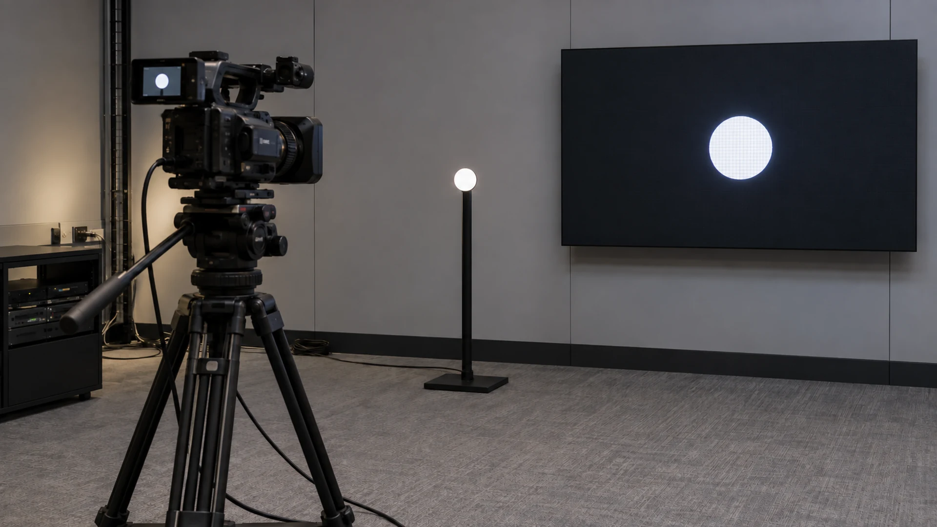
The recording setup needs care. Camera exposure, rolling shutter, the marker’s position in the recorded frame, LED scan timing, and the rule used to identify the first visible transition affect the result. A reference monitor can add its own delay, so an uncharacterized monitor is not an absolute timing reference. For tight contractual limits, use suitable optical measurement equipment and a qualified test method.
- Document the complete route and keep all required production processing enabled.
- Record source frame rate, resolution, brightness, processor mode, panel configuration, and firmware.
- Define the start event, endpoint, measurement locations, and transition-detection rule.
- Capture repeated transitions rather than selecting a single favorable example.
- Report the observed range, typical result, sampling method, and measurement uncertainty.
- Repeat after input switching, preset changes, restart, and use of the agreed backup path.
A recording at 240 fps samples time in intervals of about 4.17 ms. That interval is only the sampling step; it is not proof of 4.17 ms measurement accuracy. Report the limitations of the setup and retain the original recording. An informal phone slow-motion clip can reveal a large mismatch, but it needs a validated method before becoming an acceptance certificate.
Should synchronization and audio be tested separately?
Yes. Synchronization aligns timing between devices or outputs. It does not, by itself, demonstrate a short total delay. Two LED walls can be aligned with each other while both show an event late. Conversely, two individually fast paths can have different delays and look mismatched when placed side by side.
Check matching screen sections, input transitions, and any repeated image across the venue. Record reference signals and intentional frame delays. The LED display synchronization guide explains the coordination checks that complement this latency test.
Audio needs an integrated review at the intended listening positions. Delaying sound may improve lip synchronization for a displayed image, but it cannot remove video delay and may affect the experience of viewers who also see the live presenter. Ask the AV designer to approve the relationship between direct action, screen image, and sound for the actual seating layout.
Turn the test into a usable acceptance schedule
Agree the test before the purchase order. A requirement such as “no visible lag” leaves too much room for disagreement. Name the application, endpoints, allowed operating modes, test equipment, repeat count, environmental conditions, and the party responsible for the complete result.
| Acceptance field | What the buyer should record |
|---|---|
| Boundary | Exact source event and visible endpoint; separate component claims from full-path measurements |
| Configuration | Device models, firmware, source format, processing, canvas, receiving cards, and presets |
| Target | Project-agreed limit in milliseconds, applicable frame rate, and treatment of uncertainty |
| Repeatability | Number of trials, observed range, and handling of outliers or intermittent changes |
| Operating cases | Normal path, alternate source, required presets, restart, and backup operation |
| Evidence and ownership | Recordings or instrument logs, configuration backup, responsible integrator, correction and retest plan |
A component supplier can substantiate its hardware scope. The camera or media-server provider owns source behavior. The integrator coordinates the combined signal path, while the owner approves the intended application and acceptance limit. Assign one lead to collect evidence and resolve failures across those boundaries.
Use the table as a procurement worksheet rather than inserting an arbitrary universal limit. A broadcast, interactive, conferencing, or signage project may need different criteria. The limit should reflect the application and a demonstrated system configuration.
What should be saved after the system passes?
Preserve the signal diagram, device inventory, configuration files, test conditions, raw evidence, and signed result together. Record which settings are essential to the passing result. Include a straightforward procedure for restoring the approved path after equipment replacement.
Retest when a change can affect buffering or timing: a new camera format, switcher preset, processor mode, firmware version, receiving-card configuration, or encoder setting. A previously accepted result should not silently be applied to a materially different system. The configuration backup checklist helps keep the settings and recovery responsibilities organized.
What should you send with a latency-related RFQ?
Send the screen dimensions and native canvas, application, camera or content source, signal-flow diagram, input formats, frame rates, processing functions, controller preferences, receiving-card details if known, and backup requirements. Include the intended viewer positions and whether the audience also sees the live action.
Then state the LED display latency boundary and the proposed acceptance method. Ask for a configuration-specific response, including exclusions and evidence needed before shipment and at commissioning. Share those project inputs with Mirun so the display and control scope can be reviewed alongside the rest of the AV system.
Frequently asked questions
Does zero-frame latency mean zero milliseconds?
No. A zero-frame label can describe processing that takes less than one frame within a particular device. It does not mean that physical acquisition, transmission, processing, and light output take no time. Check the manufacturer’s numerical definition and measurement endpoints.
Can a shorter cable solve LED display input lag?
Changing ordinary cable length is unlikely to resolve a delay caused by frame buffering or video processing. Investigate converters, codecs, source settings, and processing modes. A change from an encoded link to a different transport path may matter, but that is a system change that needs its own test.
Can the factory test replace the onsite test?
A factory test can establish the proposed display system’s behavior and catch configuration problems early. It cannot fully represent a venue that adds different cameras, switchers, networks, presets, or audio equipment. Keep both tests tied to their documented boundaries.
Does enabling the fastest mode complete commissioning?
No. Recheck the required canvas, image quality, input switching, synchronization, and backup operation in that mode. Keep the measured latency result together with those functional checks so the approved configuration can deliver the whole project requirement.
Need help choosing the right LED display?
Tell us your installation scene, screen size, pixel pitch target and timeline. Mirun Hailian can help match the right product configuration.