An LED display scan rate may appear in a quotation as 1/8, 1/16, 1/32, or another ratio. Buyers often treat the number as a simple quality grade. It is not. Scan ratio describes how groups of LED rows are driven over time, but the visible result also depends on the LED package, driver IC, module circuit, refresh settings, grayscale processing, brightness target, power design, and camera settings.
The practical answer is simple: specify the required visual result and test conditions, then record the approved scan configuration. A lower multiplexing ratio can support some performance goals, but it does not automatically make a complete display brighter, smoother, or more camera-friendly. This guide explains how to compare proposals without turning one engineering parameter into a misleading pass/fail rule.
What does LED display scan rate mean?
LED display scan rate describes the share of LED rows energized during one drive step. In a multiplexed module, the control electronics switch between row groups rapidly enough that viewers perceive one stable image. For example, “1/16 scan” generally indicates that one of sixteen row groups is addressed during each step of the scanning sequence.
This is an electronic drive method, not the screen refresh rate. Refresh rate describes how often image information is refreshed over time. Scan ratio describes how the module distributes drive time among LED row groups. Driver behavior, current, pulse timing, grayscale algorithms, and receiving-card configuration connect the two, but the terms are not interchangeable.
That distinction matters when comparing an indoor fine-pitch wall, an outdoor advertising screen, and a rental cabinet. Their pixel pitch, LED package, module layout, viewing distance, brightness requirement, and service priorities differ. The most suitable drive architecture may differ as well. Start with the application and approved result, then evaluate the scan design inside that context. Buyers comparing product families can use the LED display product catalog to frame those application differences before requesting a configuration.
Is a lower scan ratio always better?
No. A lower multiplexing level—such as 1/8 compared with 1/16—gives each row group a larger share of the drive cycle, all else being equal. That can make it easier to reach a brightness or visual-performance target. However, “all else being equal” rarely applies to two different finished products.
A well-designed 1/16-scan module can outperform a poorly integrated 1/8-scan module in the conditions that matter to the buyer. LED efficiency, current settings, heat management, driver IC capability, PCB layout, calibration, masks, power supplies, and control parameters all affect the outcome. A quotation that lists the scan ratio but omits the measured configuration therefore gives only part of the answer.
| Buyer question | What scan ratio can influence | What else must be verified |
|---|---|---|
| Will the display reach the target brightness? | Available duty time for each row group | LED efficiency, drive current, thermal conditions, calibration and actual test method |
| Will dark content look smooth? | Time available for pulse and grayscale control | Driver IC, bit-depth pipeline, gamma, calibration and low-brightness settings |
| Will cameras see bands or artifacts? | Drive timing within the complete emission sequence | Refresh configuration, PWM behavior, shutter speed, frame rate and processor setup |
| Will modules be interchangeable? | Part of the module’s electrical architecture | PCB revision, driver IC, hub mapping, firmware, calibration data and connector layout |
| Will power and heat stay within scope? | Drive strategy can change electrical and thermal behavior | Average content, brightness cap, power design, ventilation and ambient temperature |
How can scan ratio affect brightness and heat?
During multiplexing, each row group receives only part of the total cycle. A design may compensate through LED selection, current, timing, optical efficiency, or a combination of these choices. That is why scan ratio and brightness are related, but one does not predict the other by itself.
Buyers should ask for the maintained brightness target at the proposed configuration, not a maximum laboratory number without conditions. The evidence should identify the module version, brightness setting, white-balance point, test pattern, ambient condition, and measurement position. If a supplier changes current or timing to reach a target, the buyer should also understand the effect on temperature, efficiency, LED stress, and warranty assumptions.
For outdoor screens, sufficient luminance must be evaluated together with sunlight, viewing direction, automatic brightness control, ventilation, and site temperature. For indoor displays, excessive brightness can make comfortable low-level operation more difficult. The relevant target is the approved operating range, not the highest number the cabinet can briefly produce.
Why does scan mode matter at low brightness?
Low-gray performance is where weaknesses in the drive system often become visible. Dark gradients may show steps, color shifts, unstable pixels, uneven module boundaries, or lost shadow detail. Scan architecture can influence the available timing, but the driver IC, grayscale algorithm, gamma, calibration, and minimum operating brightness are equally important.
Do not approve low-gray quality from a bright promotional video. Use dark gradients, near-black neutral patches, slow tonal ramps, skin tones, and the real content type. View them from the intended distance at both normal and reduced brightness. A useful test records the brightness level and configuration so that the factory, installer, and commissioning team are evaluating the same condition. Our guide to LED display low-brightness grayscale provides a more detailed acceptance sequence.
Can scan rate predict camera performance?
No single scan ratio guarantees a clean camera image. Cameras sample light over an exposure interval, while an LED wall emits according to its own refresh and pulse timing. Bands, rolling bars, color breakup, brightness pulsing, or moiré may appear when the display configuration and camera settings interact poorly.
A proper camera test uses the intended frame rates, shutter angles or shutter speeds, exposure range, resolution, camera position, and common content. Test both bright and dark scenes. If the display is intended for broadcast, virtual production, live events, worship, or executive presentations, the approved processor, sending device, receiving-card firmware, module scan configuration, and camera settings should be saved together.
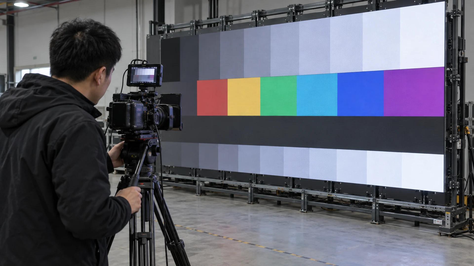
The LED display moiré and camera test guide explains why pixel structure, shooting distance, lens choice, and focus also belong in the test plan. A clean phone video is not enough evidence for a multi-camera production workflow.
What should buyers compare in a quotation?
Use the scan ratio as a configuration identifier, then compare the delivered outcome. The proposal should define the exact module and cabinet configuration rather than offering a floating specification that may change after order confirmation.
- Module model, dimensions, pixel pitch, PCB revision, and scan ratio
- LED package and driver IC model or an approved equivalent-change process
- Receiving-card model, firmware version, mapping file, and parameter backup
- Target and maximum brightness with stated measurement conditions
- Refresh and grayscale configuration used for approval
- Low-gray test patterns and acceptable visual result
- Camera test settings when the project will be filmed
- Maximum and typical power assumptions, including the test pattern
- Module, power-supply, receiving-card, and hub-board spare quantities
- Rules for notifying and approving component or PCB revisions
When comparing 1/8 scan vs 1/16 scan, keep the rest of the scope visible. If the products use different LEDs, masks, cabinet cooling, calibration methods, or brightness targets, scan ratio is not the only changed variable. Request a sample or cabinet-level test when the visual risk is material.
How should a factory sample be tested?
A useful sample test follows a repeatable sequence. First, confirm that the sample matches the proposed bill of materials and configuration. Warm the cabinet under a representative workload. Then inspect full white, primary colors, neutral grays, near-black gradients, fine detail, motion, and the buyer’s own content at the intended brightness range.
Next, measure brightness and white point using the agreed method. Check module-to-module consistency and cabinet edges from the real viewing distance. For camera projects, record several common exposure combinations instead of searching for one setting that hides a problem. Finally, export the receiving-card parameters, calibration data, processor configuration, and firmware references used for the approved result.
Approval should attach to that configuration. If the production batch changes the driver IC, PCB, scan design, LED package, mask, firmware, or control file, require a documented equivalence review or a new sample test. This protects both the buyer and supplier from arguing about a specification after manufacturing.
Why are spare modules especially important?
A scan-mode mismatch is one reason a spare module may not behave like the installed batch. A physically similar module can use a different row mapping, driver IC, PCB revision, connector assignment, calibration format, or firmware requirement. The result may be no image, incorrect colors, shifted rows, inconsistent brightness, or visible replacement patches.
Buyers should order compatible spare modules with the project and label them by batch and screen location where appropriate. Store the approved configuration files in more than one controlled location. If future substitutions are allowed, define who verifies electrical compatibility, control mapping, calibration, and visual match before the replacement enters service.
Which scan configuration fits different applications?
There is no universal best ratio, but application priorities indicate what evidence deserves more weight.
- Outdoor advertising: verify maintained brightness, thermal behavior, power assumptions, viewing angle, weather-related enclosure scope, and daytime control.
- Indoor fine-pitch rooms: emphasize uniformity, low-gray detail, comfortable dimming, color consistency, viewing distance, and service access. Review options for fine-pitch LED display projects in the context of room dimensions and content.
- Rental and touring: add cabinet interchangeability, repair speed, configuration control, spare-module compatibility, camera performance, and repeated assembly.
- Broadcast and filmed events: prioritize repeatable camera tests across the planned exposure range, saved configuration, sync design, processor workflow, and onsite responsibility.
What should be written into the purchase specification?
Write the proposed LED display scan rate into the technical schedule, but pair it with outcome-based requirements. State the application, screen dimensions, viewing distance, content, ambient light, operating brightness range, camera workflow, power limits, environmental conditions, and acceptance method. Identify which configuration files and spare parts must be delivered.
Also assign responsibility. The manufacturer should document the supplied module and cabinet configuration. The control-system integrator should preserve and deploy the approved parameters. The installer should maintain correct wiring, mapping, grounding, and service access. The buyer or consultant should define the acceptance content and operating scenarios. Camera teams should provide the frame-rate and exposure combinations they need verified.
This produces a stronger specification than “1/8 scan required” without context. It tells suppliers what must be achieved, gives evaluators comparable evidence, and creates a reference for commissioning and future maintenance.
Frequently asked questions
Is 1/8 scan better than 1/16 scan?
Not automatically. A 1/8-scan design gives each row group more drive time than a 1/16-scan design under otherwise identical conditions. Finished screens rarely keep every other variable identical, so compare measured brightness, low-gray quality, camera performance, heat, power, and reliability in the proposed configuration.
Is scan rate the same as refresh rate?
No. Scan rate describes how LED row groups are multiplexed. Refresh rate describes how frequently displayed information is refreshed. They interact through the module, driver, and control configuration, but one value cannot replace the other.
Can a supplier change the scan ratio after sample approval?
A change may require a different PCB, driver, mapping, or control configuration and can alter visible performance. Require written notification, updated technical records, and an equivalence review or repeat test before approving the production change.
What information should I send for an LED display quotation?
Send the indoor or outdoor environment, screen dimensions, pixel-pitch or viewing-distance goal, content type, camera use, brightness range, installation method, quantity, destination, schedule, power constraints, service access, and acceptance priorities. Mirun can then discuss the module and control configuration as part of a complete project scope. Contact the project team with those inputs for a comparable proposal.
Need help choosing the right LED display?
Tell us your installation scene, screen size, pixel pitch target and timeline. Mirun Hailian can help match the right product configuration.